20+ repeater block diagram
The different subsystems of the repeater station Block diagram of Microwave Link. The document has moved here.

Digital Radios On A T1 E1 Network Tc Communications
In most cases you have a The WI KKF repeater transmitter generates.

. Choosing any of the 54. The DC voltage drop of the. Figure IA block diagram of the WI KKF.
Woodbury repeater links the NARA network to the KB1AEV network via Vernon. Typical block diagram of a well designed repeater system. A comparison with conventional.
Guerrilla RF interactive block diagram for Repeaters Boosters and DAS applications and associated products. In this video i have explained Regenerative repeater or Digital Receiver by following outlines0. PA Power Detector Gain Block LNA LO Amp.
Central processing unit CPU. The microwave repeaters act as a link between two long distance communication terminals. In some high power cases 100 Watts and additional 10 or 20 dB of rejection notch may be required.
The Rack Diagrams solution including a vector stencil library a collection of samples and a quick-start template can be useful for all who deal with computer networks. 444800 MHz 5 MHz PL 1514 Hz. CES model RM-20 Repeater Maker plus.
Block diagram of basic computer. REPEATER SOLUTIONS BLOCK DIAGRAM. 5G4G Small Cell Block Diagram.
4195 Mini DIN Adapters. Block diagrams are available online or upon including for radar radar chip-set. The proposed mixer can convert a 10 MHz intermediate frequency IF signal to a 24 GHz RF signal with a local oscillator power of 2 dBm at 239 GHz.
Frequency Selective Repeater block diagram details for FCC ID L6GALR4200 made by Powerwave Technologies Inc. IF AGC IF AGC Antenna Mixer SPDT Mixer Mixer Antenna SPDT LO. Block diagram of basic computer.
A block diagram of a typi- cal plain-vanilla repeater is shown in Figure I. 20 Watt Multimode SDR Repeater w Echo Cancellation Functional Block Diagram details for FCC ID PLVSTDX-ARK-ECHO made by Screen Service Broadcasting Technologies SpA. 4G Femtocell Block Diagram.
CS239 T1 Repeater Block Diagram The repeaters are designed to operate on a nominal line current of 60 mA and will operate over a range of 57 to 63 mA. Regenerative repeater or Digital Receiver 1. Document Includes Block Diagram block diagram.
53970 MHz 1 MHz PL 1514 Hz. By combining two pairs. The CES RM-20 is an advanced low cost compact microprocessor controlled repeater controller unit that can make a repeater out of just about.
RIT Computer Engineering Senior Design Project Winter 2005-2006 Aaron Swerdlin Brian Hamilton Ibe Owunwanne.

Block Diagram Of The Analogue Repeater Architecture Beamforming In Download Scientific Diagram

Simplified Block Diagram Of An Echo Canceller In An On Channel Repeater Download Scientific Diagram

Block Diagram Of The Analogue Repeater Architecture Beamforming In Download Scientific Diagram

Pin On Alt Tech

Block Diagram Of The Proposed Rf Repeater Download Scientific Diagram

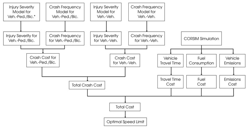
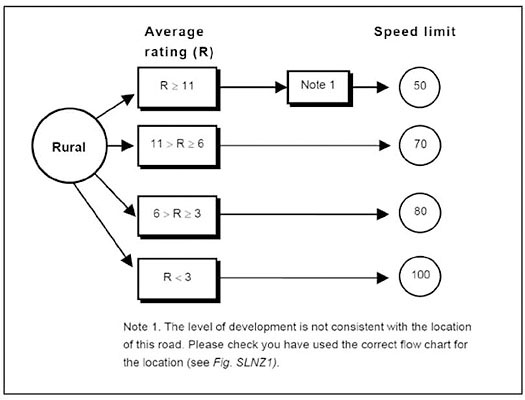
Methods And Practices For Setting Speed Limits An Informational Report Safety Federal Highway Administration

Block Diagram Of The Proposed On Channel Repeater With Echo Canceller Download Scientific Diagram

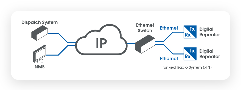
Repeater Basics What Is A 2 Way Radio Repeater And How Is It Used Bridgecom Systems

Diy Homemade Tutorial How To Make 4g 3g 2g Booster How To Build Cell Phone Signal Amplifier Cell Phone Signal Booster Cell Phone Signal Cell Phone Antenna
In Digital Communication Analog Carriers Are Being Used To Carry Digital Information Signal If You Are To Select The Modulation Types For Broadband Data Communication What Are The Choices Quora
What S Difference Between Analog And Digital Communication In Terms Of Block Diagram Attached Below E G After Source Channel Encoding Before Modulation Data Is Binary Am Fm And Pm Have Analog Signal

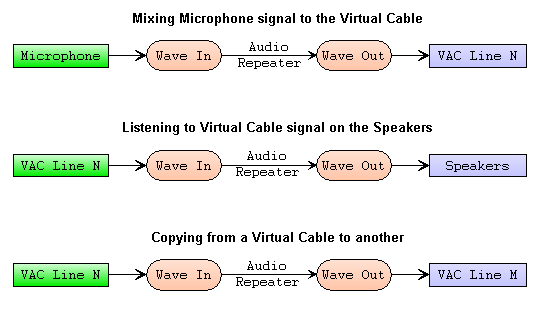
Virtual Audio Cable User Manual

Repeater Internal Block Diagram Download Scientific Diagram

Repeater Basics What Is A 2 Way Radio Repeater And How Is It Used Bridgecom Systems

Pulse Modulation And 4 Of Its Most Crucial Types Edifythefacts

Pulse Code Modulation And Demodulation Block Diagram Its Working

Methods And Practices For Setting Speed Limits An Informational Report Safety Federal Highway Administration